
What’s New
Why Does CNC Machining Accuracy Keep Changing? 7 Machine Vise Setup Problems to Check
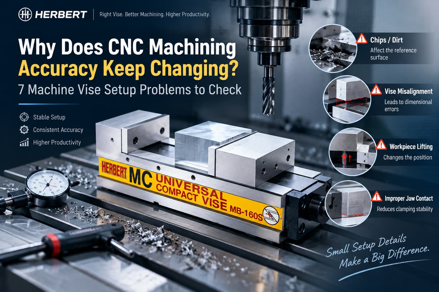
Your CNC program has not changed. The cutting tool appears normal. The machine vise is tightened securely. Yet the dimensions still vary from one part to the next.
When this happens, it is easy to suspect the CNC machine, tool wear, or programming first. But inconsistent machining accuracy can also begin much earlier in the process—at the point where the workpiece and vise are set up.
A machine vise does more than hold a part in place. It establishes the workpiece position and must keep that position stable while cutting forces act on the part. A small amount of contamination, misalignment, lifting, or inappropriate clamping can therefore become a measurable machining error.
Before adjusting offsets or blaming the machine, here are seven machine vise setup problems worth checking.
1. Is There a Chip Between the Vise and Machine Table?
One of the simplest setup problems can also be one of the easiest to overlook.
When a machine vise is removed and installed again, chips, burrs, coolant residue, or other contamination can remain between the vise base and machine table. Even if the vise appears securely mounted, contamination can prevent it from sitting correctly on the reference surface.
The result may be:
- A small angular error in the vise
- Incorrect workpiece positioning
- Variation after reinstalling the vise
- Different results between setups
This is especially worth checking when machining accuracy changes after a vise or fixture has been removed and reinstalled.
HERBERT has previously covered cleaning and routine vise care in How to Maintain Machine Vice, so we will not repeat the full maintenance procedure here. The important setup principle is simple: a precision vise cannot establish a reliable reference if the surfaces beneath it are not clean.
2. Was the Machine Vise Alignment Actually Verified?
A vise can be firmly bolted to the table and still be incorrectly aligned.
For machining operations that depend on the fixed jaw or another vise surface as a reference, even a small angular deviation relative to the machine axis can affect the resulting geometry.
This becomes particularly noticeable when machining:
- Long workpieces
- Parallel surfaces
- Features positioned relative to an edge
- Multiple parts using the same setup
A common mistake is assuming that because the vise was aligned previously, it remains aligned after removal, maintenance, relocation, or another setup change.
If accuracy problems suddenly appear after changing the setup, verify the vise position before compensating for the error elsewhere.
HERBERT's earlier guide, What Is a Machine Vise Used for?, already covers introductory information about machine vise use and setup. Readers who need those fundamentals can refer to that guide rather than repeating them here.
3. Is the Workpiece Clamped Too High in the Jaws?
Sometimes the vise itself is correctly installed, but the workpiece is not supported effectively.
When too much of the workpiece extends above the jaws, the distance between the clamping point and cutting area increases. Under cutting forces, this can make the setup less rigid.
Possible symptoms include:
- Vibration during machining
- Poor surface finish
- Dimensional variation
- Movement under heavier cuts
- Inconsistent results as cutting direction changes
This does not mean every workpiece must be positioned as low as physically possible. Tool clearance, part geometry, and machining access still matter.
The goal is to achieve a practical balance between tool accessibility and workholding rigidity.
If a machining problem becomes worse during heavier cutting or when machining features farther away from the clamping point, workpiece support and clamping height should be part of the investigation.
For applications where higher cutting loads require greater rigidity and stronger workholding, manufacturers can also evaluate whether an MC Power Vise is more appropriate for the machining conditions.
4. Are You Using the Right Amount of Clamping Force?
When parts move during machining, the instinctive response is often:
Tighten the vise more.
That is not always the right solution.
Too little clamping force can allow a workpiece to shift under cutting forces. But excessive clamping force can also create problems, particularly with thin-wall, lightweight, hollow, or easily deformable components.
A workpiece may be dimensionally correct while clamped but change slightly after the vise is released if excessive clamping force has elastically distorted it.
That can create a frustrating situation:
The part measures correctly during one stage of the process, but the final dimensions change after unclamping.
Instead of simply maximizing clamping force, consider:
- Workpiece material
- Wall thickness
- Geometry
- Jaw contact area
- Cutting load
- Required machining tolerance
For demanding milling applications, selecting a vise capable of providing stable and controlled workholding can be more effective than simply applying more operator torque.
HERBERT has previously discussed this topic in Want to Improve CNC Milling Stability? These Two Vises Will Enhance Precision and Reduce Errors!. That article compares different workholding approaches for improving CNC milling stability, so the detailed vise-selection discussion does not need to be repeated here.
5. Is the Workpiece Actually Seated—or Has It Lifted?
This is one of the most important problems to check when a workpiece appears securely clamped but machining accuracy remains inconsistent.
During clamping, movement of the jaw and the interaction between the jaw and workpiece can cause the part to lift slightly away from its intended locating surface.
The vise may feel tight.
The workpiece may appear secure.
But if the workpiece is no longer fully seated against the reference surface, its actual position has changed.
That small change can affect:
- Parallelism
- Feature height
- Depth dimensions
- Positional accuracy
- Part-to-part consistency
This is especially relevant when operators experience the exact problem described in the title of this article:
“The vise is tight, so why are the dimensions still changing?”
Because HERBERT has already published a dedicated guide on this issue, we do not need to repeat the complete mechanism and solution here.
For a deeper explanation, see How to Eliminate Workpiece Lifting in CNC Machining: A Guide to the HER-BERT VCP Series MC Vise. That article focuses specifically on workpiece lifting and the workholding design used to address it.
6. Are the Jaws Making Proper Contact with the Workpiece?
Another common source of inconsistency is the relationship between the jaw and the actual workpiece geometry.
A vise may generate sufficient clamping force, but that force still needs to be transferred through appropriate contact surfaces.
Problems can occur when:
- The jaw contacts only a small portion of the part
- The workpiece surface is irregular
- Burrs interfere with seating
- The jaw configuration does not match the workpiece geometry
- The workpiece is supported differently from one setup to another
This is why clamping force alone should never be used as the only measure of workholding quality.
For repetitive production, the contact condition should also be repeatable from one workpiece to the next.
If Part 1 is positioned slightly differently from Part 20 because the contact or locating condition changes, even a highly accurate CNC machine will reproduce the machining path relative to a workpiece that is no longer in exactly the same position.
Workpiece geometry should also influence vise selection. For applications requiring repeatable centering from both sides, a self-centering vise may be worth evaluating rather than trying to make a conventional jaw arrangement work for every part geometry.
7. Did You Verify the Setup After Changing the Workpiece?
This final problem becomes particularly important in batch production.
The first part may be set up carefully, measured, adjusted, and verified. Once production begins, however, operators may assume every following workpiece will automatically reproduce the same condition.
That assumption only works if the workholding condition itself remains repeatable.
Between parts, consider whether anything has changed:
- Has a chip reached a locating surface?
- Is the new workpiece fully seated?
- Is the clamping position the same?
- Has the contact condition changed?
- Is there a burr on the workpiece?
- Has the vise or jaw condition changed?
If the first part is accurate but later parts gradually become inconsistent, the problem may not be the original setup. It may be how consistently that setup is reproduced during production.
When the production process also requires frequent vise, fixture, or pallet changes, setup repeatability becomes an even larger issue. HERBERT's Quick Change Systems are designed to support faster and more repeatable workholding changes.
For a more detailed discussion of this topic, see Reducing Downtime: A Manufacturer’s Guide to CNC Quick Change Systems.
A Quick Machine Vise Setup Checklist Before Starting CNC Machining
When machining dimensions begin changing unexpectedly, checking the setup systematically is usually more useful than immediately changing several machine parameters at once.
Before starting or restarting production, check:
| Checkpoint | What to Verify |
|---|---|
| Vise mounting surface | No chips, burrs, or contamination between reference surfaces |
| Vise alignment | Vise/reference jaw is correctly aligned with the required machine axis |
| Workpiece position | Part is located consistently against the intended references |
| Clamping height | Workpiece has adequate support and unnecessary overhang is minimized |
| Clamping force | Sufficient to resist cutting forces without unnecessarily deforming the part |
| Workpiece seating | Part remains fully seated after clamping |
| Jaw contact | Contact surfaces match the workpiece and provide stable support |
| Setup repeatability | Each replacement workpiece reproduces the intended locating and clamping condition |
The purpose of this checklist is not to replace your shop's inspection procedure. It is to help separate a workholding problem from a machine, tooling, programming, or process problem.
What If the Setup Is Correct but Accuracy Still Changes?
If all seven items have been checked and the workpiece still shifts, lifts, vibrates, or produces inconsistent dimensions, the next question should not automatically be:
“How much tighter can we clamp it?”
Instead, ask:
“Is the current machine vise suitable for this machining condition?”
Different applications place very different demands on workholding.
Heavy cutting may require greater rigidity and clamping capability. Thin or easily distorted parts may require more controlled force. Multi-axis machining may prioritize access and repeatable centering. High-volume production may place greater importance on repeatability and setup efficiency.
This is where choosing the appropriate workholding solution becomes important.
HERBERT provides different vise designs for these requirements, including MC Power Vises, MC Mechanical Vises, Pneumatic and Hydraulic Vises, and Self-Centering Vises. The objective is not to use the most powerful vise for every application, but to match the workholding characteristics to the actual machining problem.
For example, HERBERT has already explained how MC Power Vises and Self-Centering Vises address different CNC milling requirements in Want to Improve CNC Milling Stability? These Two Vises Will Enhance Precision and Reduce Errors!, so manufacturers evaluating those options can refer to that comparison rather than treating every accuracy problem as a need for higher clamping force.
FAQ
Why do CNC part dimensions change even when the program stays the same?
A CNC program is only one part of the machining process. Changes in tool condition, machine condition, temperature, workpiece material, positioning, and workholding can all affect the result. If dimensional variation appears after changing or reclamping a workpiece, the vise setup and workpiece location are worth checking.
Can a machine vise cause machining accuracy problems?
A vise can contribute to machining errors if it is incorrectly aligned, contaminated at its mounting or locating surfaces, unable to hold the workpiece securely, or if the workpiece lifts or deforms during clamping. However, machining accuracy is influenced by the entire process, so the vise should be evaluated as one part of the system.
Why does the first CNC part measure correctly but later parts vary?
If the first part is correct but subsequent parts differ, check whether each replacement workpiece is being located and clamped under the same conditions. Chips, burrs, inconsistent seating, changing contact conditions, tool wear, and other process variables can all contribute to part-to-part variation.
Does higher vise clamping force always improve CNC accuracy?
No. The vise needs enough force to prevent unwanted movement under cutting loads, but excessive clamping force can deform some workpieces. Stable support, proper jaw contact, workpiece geometry, material, and cutting conditions should all be considered together.
Conclusion
When CNC machining accuracy keeps changing, the machine itself is not always the first place to look.
A chip beneath a reference surface, slight vise misalignment, excessive workpiece overhang, incorrect clamping force, workpiece lifting, poor jaw contact, or inconsistent setup reproduction can all affect where the part actually sits during machining.
The important question is therefore not simply:
“Is the vise tight?”
It is:
“Is the workpiece positioned, supported, and clamped in exactly the condition the machining process requires?”
Checking these seven areas can help manufacturers identify workholding-related problems before unnecessary changes are made to programs, tools, or machine parameters.
When the setup has been verified but clamping stability remains a limitation, the next step is to evaluate whether the current vise matches the workpiece, cutting load, machine configuration, and production requirements.
HERBERT Enterprise Co., Ltd. provides a range of machine vise and workholding solutions for different CNC machining requirements. Contact HERBERT to discuss your workpiece and machining conditions and identify a suitable workholding solution.